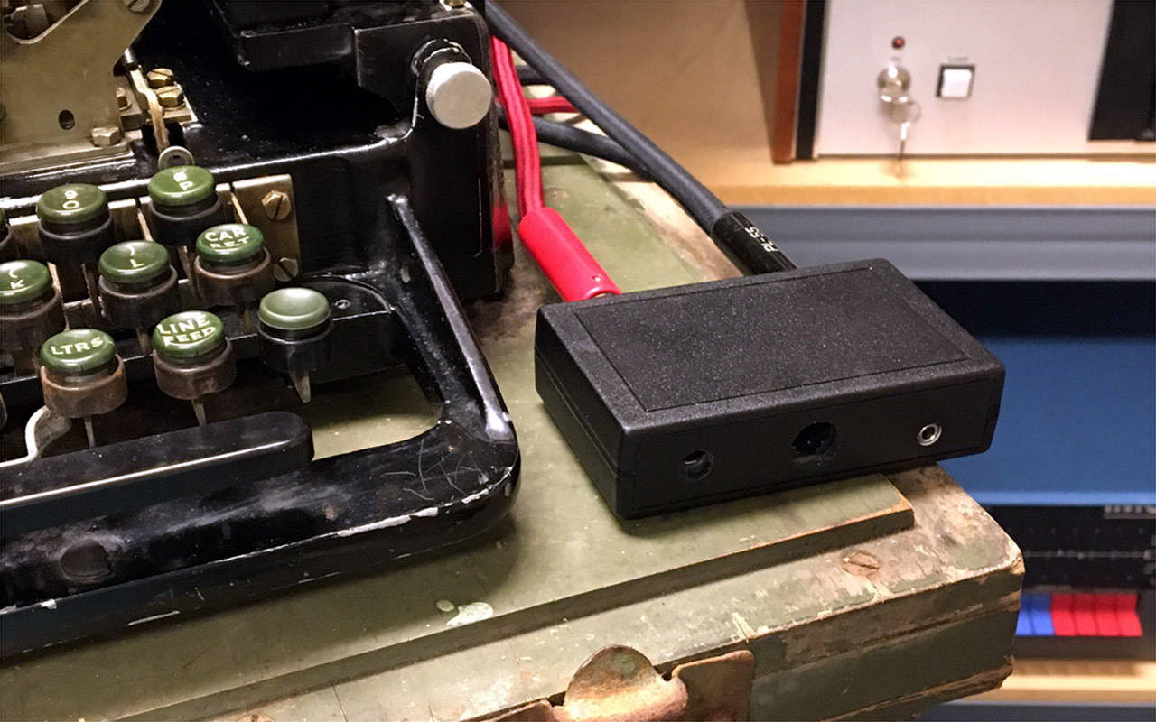
Easily Drive a Model 15 Teletype from a Computer or AFSK Data Feed
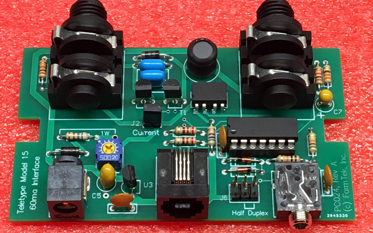
This board makes it easy to interface a Model 15 Teletype to a computer – or any device that uses RS-232 and ASCII for communication. The board also has an audio input for accepting AFSK data (e.g., an ITTY feed) which it will demodulate and use to drive the Teletype. The interface can also be used with the Model 28 Teletype when the M28 is configured as required.
The board generates the 60ma loop current required by the Teletype without the need for a high voltage loop supply or high power (hot!) components.
HOST INTERFACE
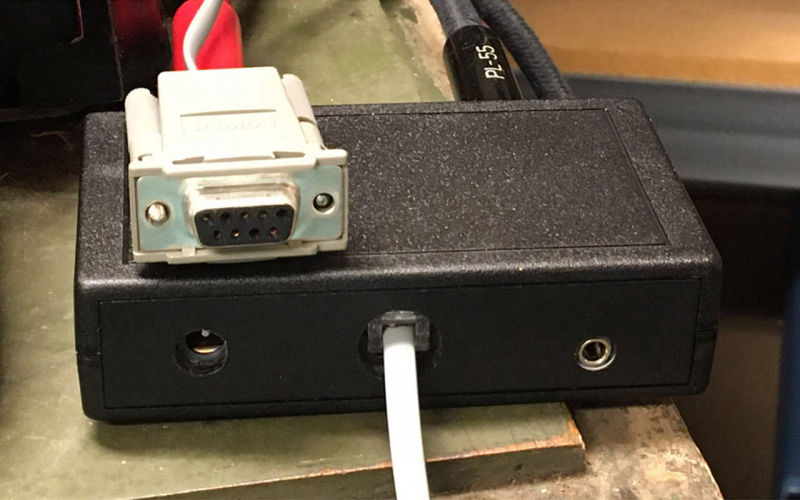
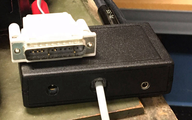
The host interface is RS-232, 9600 baud, 8N1, using the ASCII character set. An RJ-14 modular connector on the interface easily allows switching between a modular DB-9 or DB-25 connector for the host connection. The host is throttled by a flow control line from the interface board.
The audio input supports line level AFSK data (2125Hz Mark, 2295Hz Space) for ITTY or RTTY. Connection is via a 3.5mm headphone plug.
TELETYPE INTERFACE
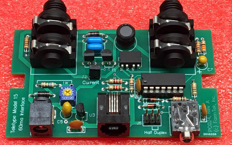
The Teletype interface supports 60ma current loop, 45.5 baud, using the Baudot (US-TTY or ITA2) character set. The interface can also be configured for 50 or 75 baud. The Teletype must be wired for full duplex operation (separate transmit and receive loops). The interface is specifically designed for use with the Model 15 neutral signaling configuration (pulling or holding magnet). Connection to the Teletype is through separate 1/4” headphone jacks for send and receive. Half duplex operation can be enabled on the board, but the loops remain electrically separate.
“Escape” sequences, started with the blank key on the Teletype keyboard, allow generation of ASCII characters not present on the Teletype keyboard (e.g., control characters, + * = ^ etc.).
MISCELLANEOUS
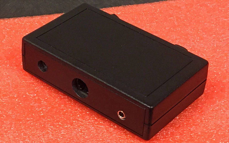
The interface is fully powered by a small 15 volt AC adapter. The board is designed to fit in a Pac-Tec JM-42 case. The board generates virtually no heat, so the case can be closed.


