Southwest Technical Products Corporation
Newsletter / Catalog circa 1970 (see actual pages
below.)
Lambert Labs, LTD. Acquired
Southwest Technical Products Corp. is happy to announce the acquisition of
Lambert Labs Limited of Westfield, New York. Lambert Labs manufactures several
unique instruments of superior quality at prices that cannot be matched by the
major instrument manufacturers.
Readers of the popular electronic magazines will remember the pulse generator,
low distortion audio oscillator, wide band preamp, etc. that were products of
Lambert Labs. Southwest Technical Products will supply these kits and other
designs by Mr. Jim Bongiorno of Lambert Labs. The first new kit to be offered
will be a "Tone Burst Generator." This design has features not available on any
instrument of this type now available. It includes digital control circuits to
allow pre-selection of the exact number of cycles to be included in the tone
burst. The generator can switch between two different burst frequencies or
deliver a single burst as desired. This instrument should be extremely valuable
to anyone doing serious testing of audio equipment.
Mr. Bongiorno is one of the leading designers of audio equipment in this
country. He has done consulting work for several major audio manufacturers and
was employed by Marrantz before organizing his own company. The "Guest"
editorial in this edition contains some of his ideas on current amplifier
designs and distortion. He is currently working on several new audio projects
that we will begin to offer during the new year. These designs will offer new
ideas in audio circuits and will all be advances over current designs.
100% Testing and Plug-In Readout
All counters and decoder drivers used in the NX and NUM series counters are
100% tested for proper operation. You can be sure that any integrated circuits
received in these kits will operate properly, provided assembly is done
correctly.
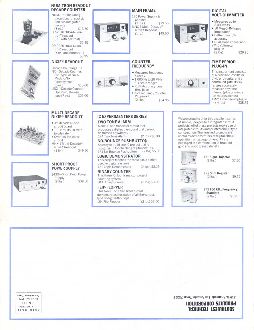
Our Nixie Counter series is now being supplied with plug-in type readout tubes
and sockets, at the same bargain price of $15.00 per decade. This makes it
practical for anyone to own digital instruments. Our one board, multidecade
Nixie readout system (MNX-1) has also been reduced in price. It is now only
$49.50.
The NUM segmented readout kit has been reduced to $13.50, less readout. This kit
may be used with the "RCA" Numitron readout tube, the Monsanto MAN-1 light
emitting diode readout, or to drive traics for large segmented displays such as
are used on scoreboards. The output of the NUM decoder is capable of driving
triacs with ratings up to 8 amps on each segment. This is done by simply
connecting a 220 Ohm resister between 7447 decoder chip output and the gate
terminal of the triac.
Our new Up-Down counter #UNX is now ready. This counter will be described in the
Feb. 1971 issue of "Popular Electronics" magazine. Without question this is the
most versatile counter available today. Not only will it count both backward and
forward, but it can also be connected to count any modulo desired from 2 to 10
It also has parallel data inputs so that a number may be preset into the counter
before counting begins. Counting speed is up to 32 MHz.
How Many Digits?
One of the most often requested pieces of information here at Southwest
Technical Products Corp. is "How do I made a readout system with four (five,
six, etc.) numbers, using your circuits?" In a digital readout system all parts
of the system should have similar accuracies if the system cost is to be kept
within reason. The accuracy that is chosen will determine the number of digits
that can be used in the readout before they become meaningless. Thus if we
choose to use a 60HZ. line time base to build an economical counter we are
limited by the accuracy of the power lines frequency. In most cases this is
approximately 0.1%, or three digits. Now we could add another digit to the
readout, but the reading on this tube would be meaningless since the time base
used to make the reading was only accurate to three places (1%). Similarly, we
could build a voltmeter with four, five or six digits, but if the analog to
digital converter was only linear, or accurate to .1%, again we would have a
reading with several meaningless numbers due to limitations of the converter
circuit.
If your requirement is for a frequency counter only, which will give you a
reading accurate to four, or five places; the RPT-1 time base can be used. This
time base has a crystal oscillator which can be adjusted to beat with WWV, or
other primary standards to give you an accuracy of .001%. As long as the ambient
temperature remains fairly constant you can get readings out to five places with
such a system. Greater accuracies would require a more accurate (expensive)
crystal and an oven to hold it at a constant temperature.
The RPT-1 time base can also be used to build a "Sports Timer" type instrument
with either Nixie, or Numitron readout. Construction would be similar to the
lamp readout device described in "Popular Electronics" Oct. 1968. Reprints are
available.
THE MYTH CONCERNING DISTORTION
by Jim Bongiorno
In referring to distortion, there is one question that I am asked more often
than all others concerning audio. This question is "Why is there still such
great concern over the distortion of amplifiers, when the distortion of pickups
and loudspeakers is so much worse?" This is not an easy question to answer, but
there are many valid reasons for continuing the research into ultra low
distortion amplifiers.
Firstly, loudspeakers and pickups are getting surprisingly good in recent years.
Also, when considering today's finer loudspeakers, we are almost always dealing
with a multiple element system with a complex cross-over network. Since we are
therefore limiting the working frequency range of each separate element, we can
safely say that very high order distortion products will be greatly subdued
(intermodulation). Another of the problems (related to hearing) is the
psychological adjustment that the ear makes when you are listening. This
adjustment factor is heavily dependent upon the musical awareness of the
listener, i.e.: education hearing range, environment, life style, etc. It is not
surprising to find loudspeakers today with distortion factors around 1% or so at
normal listening levels. This fact indicates that our amplifiers must surely
have orders of magnitude lower distortion factors.
One fault that has been made and continues to be made is the improper
interpretations of the results of distortion measurements. In other words are we
stating the proper quantities of distortion and therefore, are the present
subjective results correct? The answer is definitely NO, and I further believe
that we need a new set of references in regard to proper measurement techniques
and interpretive analysis. In the following examples, it should become very
clear that a change in values is needed.
The three major sources of distortion that are found in current transistor
amplifiers are asymmetrical distortion, primary cross-over distortion and
secondary crossover distortion. All of these produce distortion products that
are primarily outside the audio range and which have a much larger effect on the
sound than the normal distortion analyzer indicates. These distortion products
must be viewed at the output of an analyzer with a bandwidth of a Megacycle, or
more, to appreciate their seriousness. The average reading metering circuit on
the analyzer will hardly notice these "burst" of distortion, but a well trained,
or even not so well trained ear can detect them rather easily.
Asymmetrical distortion is something that has never been discussed in print
before, at least to my knowledge. The sound of this kind of distortion is very
gritty and much like intermodulation distortion and like intermodulation, it
only requires very small amounts to be objectionable. It can only be observed
when displayed in X-Y fashion on an oscilloscope. It looks very much like normal
harmonic distortion with the exception that one side or lobe of the pattern
usually has a long tail on it. This kind of distortion arises mainly from
unbalanced gain stages within the amplifier. It almost never occurs in a
balanced bridge (full wave bridge). It is also very common in amplifiers that do
not have differentially coupled stages. It will almost certainly be present in
an output stage that is not driven by equal current on both positive and
negative half cycles. With all of these conditions present, the amplifier has
different gains (open loop) between the positive and negative half cycles. Also,
the open loop distortion products will almost never be proportional. Therefore,
the feedback loop doesn't know the difference between the positive or negative
half cycle, which results in unequal distortion reduction. Thus we end up with
this kind of asymmetrical distortion. Also, some designers say that they don't
need to match output transistors. This is definitely a fallacy. Furthermore, not
only do the outputs need matching, so do the drivers. There is one factor
however, that alleviates this situation a little. All output stages are usually
unity gain stages of one sort or another (emitter followers). The designers
therefore, put all of the voltage gain (or as much as possible) in the stages
preceding the output stage. Also the open loop gain is made as high and linear
as possible. It would however, still be better to match the devices and if the
time and equipment (money?) are available, it should be done. But don't be
mislead. We are talking about a difference in distortion factors of maybe .02%
to .04%. This increase is almost always of the asymmetrical type. The cost added
to the product for this type of matching and selection could well add up to an
additional 50%, as it takes lots of time.
Primary cross-over distortion can be eliminated by operating the output stage
class AB and at a high enough idle current so that both transistors are never
off at the same time. Idle current must be rather high (over 50 Ma.), unless an
active current source driver is used, to insure that no cross-over distortion
can occur. This results in considerable heating of the output transistors and
compensating diodes must be used to prevent thermal runaway of the output stage.
The problem is that these diodes can overcompensate and cause the amplifier to
sound bad when it's output transistors are in certain temperature ranges.
Perfect tracking is difficult to obtain and if design idle current is on the low
side, this distortion can occur. A driver circuit using an active current
source, rather than a bootstrap capacitor and split load resistor in the driver,
will minimize this type distortion, if it occurs. A compensated current source
driving the output transistors will insure that cross-over distortion cannot
occur.
Another type of distortion which is also very unpleasant, and also very rarely
mentioned, is secondary cross-over distortion, NOT to be confused with the
primary cross-over distortion which is associated with biasing. There is no type
of biasing that will alleviate secondary crossover except pure class A
operation. One company has used sensing power diodes in the output stage which
effectively lowers this kind of distortion but it does not completely eliminate
it. It is also possible to run the drivers only, in class A but this is quite a
waste of power and they will also be running at fairly high junction
temperatures. A much easier solution is to use 100 Megacycle devices as the
drivers instead of the more common single diffused devices that most
manufacturers use. This results in an open loop bandwidth which is much, much
greater than most amplifiers, and consequently there are not time-delay, stored
switching transients in the output stage. Another benefit is the fact that the
output transistors can be biased completely off with no idle current and no ill
effects. Of course this results in 100% freedom from any temperature problems
associated with the need for biasing.
NEW MEDIUM POWER AMPLIFIER
 Southwest Technical Products Corporation is happy to announce the latest
addition to our line of power amplifier
kits. Our answer to your requests for a really "great" amplifier in the 30 to 50
Watt range is now ready - the "PLASTIC TIGER."
Southwest Technical Products Corporation is happy to announce the latest
addition to our line of power amplifier
kits. Our answer to your requests for a really "great" amplifier in the 30 to 50
Watt range is now ready - the "PLASTIC TIGER."
Plastic Tiger uses the same basic circuit as is used in our "Universal Tiger,"
combined with economical complementary silicon plastic output transistors. The
result is an amplifier with performance and stability that is outstanding in its
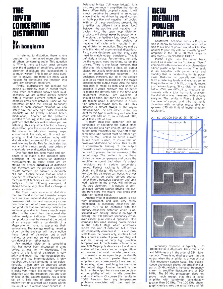
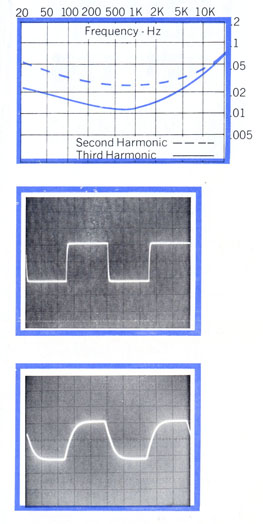
power class. Distortion is typically well below 0.1% at listening levels and
reaches something thing in the order of 0.1%, or slightly more, just before
clipping. Since distortion levels below .05%, are difficult to measure
accurately with a total harmonic analyzer, the distortion was measured with a
wave analyzer. The results in Figure 1 show a low level of second and third
harmonic distortion with no other measurable responses (-75 db limit of
instrumentation resolution).
Frequency response is typically 1 to 100,000 Hz @ -1 db points. The circuits
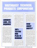
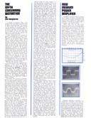
rise and fall times are in the order of 2.5 micro-seconds. There is no ringing present in the output when the amplifier is driven
with a high frequency square wave. The oscilloscope photograph shows the
amplifier output at 10 KHz which is the usual frequency shown in amplifier
literature and at 100 KHz. The 10 KHz photograph does not prove much except that
this a good amplifier with bandwidth considerably greater than 10 KHz. The 100
KHz photograph clearly shows the actual rise and fall times and the clean well
damped response of the amplifier. Note the low amplitude of the small ripples on
the top of the square wave. It is not likely that you will see very many
amplifier manufacturers publish test data showing square wave response at this
frequency. It is quite easy to hide a fast spike on the leading edge of the
square wave, or a few cycles of 500 KHz ringing, if you use a frequency of 10KHz
and blur the picture a bit with bad focus, or a touch too much intensity. Of
course we know that no one would do a thing like this. At 100 KHz, the rise time
is clearly shown since we are looking at the first 10% of the waveform we saw at
10KHz; any spikes, or ringing cannot be hidden. Of course the fact that many
amplifiers would react to a 20 Volt P-P output at 100KHz with a flash, or puff
of smoke will also deter the universal acceptance of this particular test.
This kit will be priced the same as the #160 kit it replaces, $18.50 per channel
and $55.00 for a two channel kit with chassis and power supply. We do not know
of anything that compares with this amplifier at anywhere near this price.
Here are 96 dpi JPG page images.

Catalog and Brochure
Index
Michael Holley's
SWTPC Collection Home Page
This page was last edited
October 30, 2005